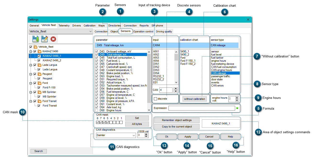
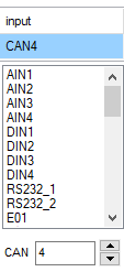
Here you can see the list of possible connections to a tracking device. Different models of tracking devices may have different amounts and types of inputs.
Please note: you can find the information about the mapping of tracking device inputs and sensors in the Tracking device installation report (this document may have another name, and it is provided by montage workers after the installation of the tracking device on the object).
Discrete sensors (from the latin word discre-tus– intermittent, parted) are sensors that receive signal. Discrete sensors can only have two variants of signal on the channel output - log 0 and log 1.
A limit switch can serve as an example of such a sensor. A limit switch has two states: closed and open. A discrete sensor can have several output channels, each of them has one of these two states.
When configuring a discrete sensor, one needs to select one of the corresponding inputs of tracking device: DIN1, DIN2, DIN3 or DIN4. The current state of a discrete sensor will be displayed in the Telemetry Panel in a checkbox.
This is an example of the state of a discrete sensor for a dump body lift:
In this text field one can input a formula for calculation of parameters' values in case more than 2 inputs of tracking device are used to calculate some value (for example, we use a fuel sensor in each of two tanks, and we sum the values received from each sensor).
Here one can select an algorithm for the interpretation of data received, depending on the type of a measured value.
For example, if fuel level is measured, then we need to eliminate the values received when the battery is disconnected and connected again, because these values are not accurate.
For every sensor type, an individual algorithm for values correction is applied.
For the type of sensors CAN fuel consumption, an additional column Analysis is available in the Chart tab.
For every discrete sensor, it is possible to set a type of event sensor.
As an example, let's look at the configuration of the parameter Dump body lift:
1. Let's set the type of the event sensor:
2. We need to configure the sensor Dump body lift with the tool Event editor.
The data will be displayed in the Telemetry Panel in the tab chart
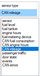
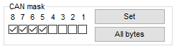
The system allows to read messages from the CAN-bus of a vehicle. For this, one needs to set the association of a bit-mask (CAN mask) to the transmitted parameters of the CAN-bus. It allows to get data from the vehicle's on-board system (fuel level, fuel consumption, speed, coolant temperature, etc) without installation of additional sensors.
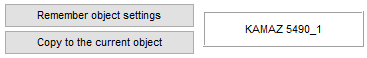
The command "Remember object settings" copies all the settings of the object's sensors. To apply the same settings to another object, you need to select this object in the vehicle fleet structure and click "Copy to the current object".